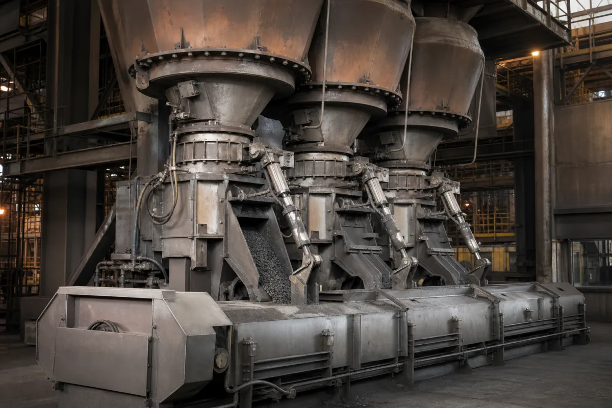
Discharge system for a direct reduction shaft furnace: bottom feeder, seal leg and seal gas for DRI and HBI
The bottom end of a DRI shaft furnace · burden feeders, raking arms and scraper bars, the bottom seal leg and its seal gas, product discharge chamber and surge bin
A gas-based shaft furnace reduces a moving bed of pellets and lump ore, and the whole bed descends only as fast as the bottom discharge removes product. The discharge system therefore sets the furnace throughput, has to pass hot, sticky reduced iron without crushing it, and must let the product out while the reducing gas, under pressure, stays in. Patents from Thyssen, Nippon Steel, Midrex and Primetals show the three parts to specify: the feeder that moves the burden, the seal leg and its seal gas, and the chamber that screens and buffers the product.
The equipment that removes reduced iron from the bottom of a direct reduction shaft furnace: discharge tables, scraper bars, raking arms and other bottom feeders, the bottom seal leg with its seal or barrier gas supply, and the product discharge chamber, screens, surge bins and rate feeders up to hot briquetting or melter charging. Complete gas-based DR plants, with reducing gas generation and module capacity, are covered on the Direct reduction shaft furnace page. Briquetting presses, DRI coolers built as separate vessels, and slag or ash discharge from other furnaces are outside this page.
CNFX editorial research · Sources checked October 12, 2026 · 4 sources
Moving the burden out: reciprocating scraper bar, raking arms or a converging point outlet
Each feeder design answers the same problem differently: how to take product evenly from the full cross-section of the shaft without the feeder carrying, and crushing, the weight of the bed above it.
Thyssen's US 3,831,787 describes a discharge table lying horizontally below the base of the sponge-iron column and supporting it, with a scraper bar or plate reciprocating beneath the column to push sponge iron alternately to outlets on either side; the bar is driven by rods that pass through floating bearings fitted with gas-type seals and motion-compensating members. [1]
Nippon Steel's US 4,129,289 lists the drawbacks of a reciprocating plate or rotary table that carries the whole charge load: high load, crushing of product by friction between particles, and long repair times. Its alternative is a fixed bottom of larger diameter than the shaft, spaced below the wall so that pellets of 10 to 30 mm can flow through the gap and settle at their angle of repose outside the load path; raking arms swung within a limited angle (30° in the patent's example) rake this pile off the edge into a closed space, from which a valve passes it on. Six such devices round the furnace can run together or in sequence to vary the discharge, the arm is set about two times the average particle size above the bottom to limit crushing, an adjustable skirt changes the gap, and the arm pivots in a frame cooled by a water jacket with a replaceable outer arm section. [2]
Midrex's US 7,938,882 shows the shaft ending in a converging discharge section with a point outlet through which all hot DRI leaves, and places the discharge feeder that controls the rate in a product discharge chamber below an insulated duct. [3]
State the product (cold DRI, hot DRI or feed to HBI), particle size range, discharge rate range, product temperature, furnace pressure at the outlet, the feeder type proposed, wear parts and how they are changed, and cooling of drives and bearings.
02
The bottom seal leg: dropping furnace pressure to atmospheric with seal gas
Below the feeder, the column of product in the discharge duct is itself the seal; gas injected into it is what makes that seal work.
In Midrex's description, the insulated duct between the shaft and the product discharge chamber acts as a dynamic seal leg that reduces the pressure from up to 3 barg in the converging section to at or about atmospheric at the chamber. Sealing gas injected into the leg flows both ways: upward to keep reducing gas in the furnace, and downward to create the pressure drop through the hot DRI. The sealing gas may be nitrogen or a dry flue gas with minimal oxidants, and it is vented from the chamber to dust collection. [3]
Primetals' US 12,378,616 B2 explains why the choice of seal gas matters: dried reformer flue gas, which “contains largely nitrogen and carbon dioxide but also relatively small proportions of H2O and oxygen,” “is often used as barrier gas,” but its CO2, water vapour and residual oxygen reoxidise hot metal at about 500–750 °C, lowering carbon and metallization. The patent supplies the bottom seal leg first with pure nitrogen (technical-grade nitrogen or a nitrogen/argon mix) from a nitrogen generator and adds treated flue gas from a compressor only when demand exceeds the generator's capacity; it notes that peak demand can reach twice the normal amount. In its example, the supply line runs at about 3 bar in normal consumption, a drop to 2.9 bar opens the valve for treated gas, and a pressure-maintenance valve holds the generator outlet at 7 bar. [4]
Editorial calculation: a nitrogen generator sized only for normal seal-gas consumption would cover half of a peak at twice that amount; the Primetals arrangement fills the other half with treated flue gas rather than oversizing the generator. [4]
Ask for the seal gas composition and dew point, normal and peak flow, supply pressure, the pressure profile along the seal leg, how loss of seal gas is detected, and where the vented gas goes.
03
From the discharge chamber to briquetting or the melt shop
For hot DRI the discharge system continues past the seal leg into screening and buffering, because briquetting presses and melter charging both need steady, clean feed.
Primetals names hot compaction, for example briquetting, after discharge as a way to limit reoxidation by air or water vapour, which is why inert handling between the shaft and the briquetting press is part of the discharge system. [4]
Element
What the patent describes
Source
Discharge feeder in the chamber
Controls the discharge rate; varied to keep the level in the chamber's converging section between high and low limits
All hot DRI passes through to remove hard clusters and tramp material that would harm hot briquetting machines working at high hydraulic pressure and close tolerances
Paste it into your enquiry below or into an email to a maker, then replace every bracket.
Furnace: [process; shaft diameter at the outlet; operating pressure]
Product: [cold DRI, hot DRI or HBI feed; size range; temperature]
Rate: [normal and maximum t/h; turndown]
Feeder: [scraper bar, raking arms, rotary or point outlet; wear parts; drive and cooling]
Seal: [seal leg length; seal gas type and dew point; normal and peak flow; supply pressure]
Downstream: [screens; surge bin; feeders to briquetting or melter; dust collection]
Explore company information and manufacturing capabilities, then discuss the scope of your project with a relevant supplier.
Share this page
Compiled and source-reviewed by the CNFX editorial team.
Each manufacturer above links to the page on that company's own website where the product is listed, with the date we checked it. How we source and review
· Page last updated 13 October 2026
Buyer questions
What does the seal leg under a DR shaft furnace do?
It is a column of product in an insulated duct, injected with seal gas, that drops pressure from up to 3 barg in the furnace outlet to about atmospheric at the product discharge chamber while keeping reducing gas in the furnace. [3]
Why use nitrogen rather than flue gas as seal gas?
CO2, water vapour and residual oxygen in flue gas reoxidise hot metal at about 500–750 °C, reducing carbon and metallization; Primetals supplies nitrogen first and adds treated gas only at peaks. [4]
How do bottom feeders avoid crushing the DRI?
Nippon Steel lets product flow out under the wall onto a wider fixed bottom and rakes off only the pile outside the load path, with the arm about two times the average particle size above the bottom. [2]
Sources and what still needs a direct check
Sources checked 2026-10-12. Four patents, from Thyssen, Nippon Steel, Midrex and Primetals, describe discharge feeders, seal legs and seal gas supply; they show designs that have been claimed, not the equipment of any one plant.