Editorial Technical Reference

Flow Control Device (Slide Gate or Stopper Rod)

This page explains how Flow Control Device (Slide Gate or Stopper Rod) is classified within Basic Metal Manufacturing. Technical values and manufacturer relationships are research references; confirm the current specification and supplier evidence for each order.

Technical Definition & Core Assembly

A device used to regulate the flow of molten steel from the tundish to the mold during continuous casting.
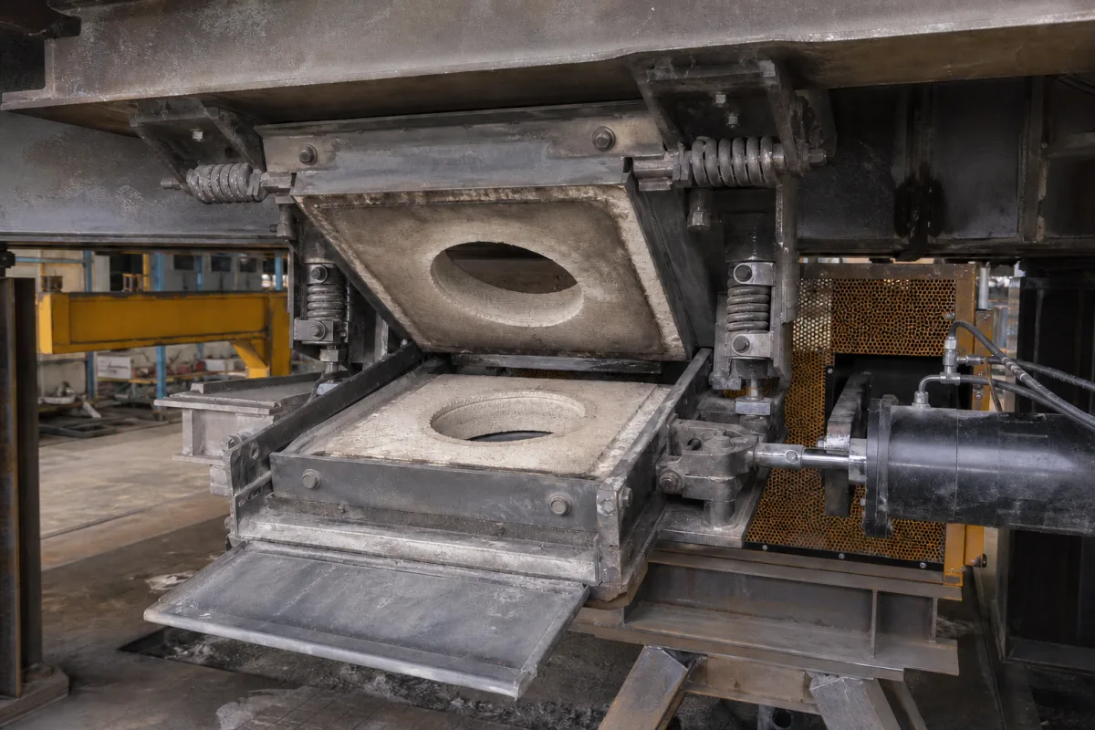
Representative product image. Confirm appearance and specifications with the manufacturer.

Product Specifications

Technical details and manufacturing context for Flow Control Device (Slide Gate or Stopper Rod)

Definition
This flow control device is a critical component of the tundish in continuous casting systems. It precisely regulates the flow rate of molten steel from the tundish into the mold, ensuring a consistent, controlled stream essential for maintaining steel quality, preventing slag entrapment, and achieving the desired casting speed and strand geometry. The device is available in two primary configurations: a slide gate or a stopper rod. The slide gate uses a sliding plate with an aperture; aligning this aperture with a fixed plate controls the open area. The stopper rod is a refractory rod that is raised or lowered into a nozzle seat (collector nozzle) in the tundish bottom to throttle the flow. Both methods allow for precise, often automated, adjustment of the molten metal flow. The device is designed for use in basic metal manufacturing, specifically in continuous casting operations. It is a component that must be selected based on specific application requirements, including nominal size (50–150 mm), operating pressure (1.0–1.6 MPa), operating temperature (1500–1600 °C), flow rate (0.5–5.0 t/min), stroke length (50–200 mm), positioning accuracy (±0.5 mm), response time (0.1–0.5 s), actuator type (electric or hydraulic), control voltage (24 V DC ±10%), ingress protection (IP54–IP65), refractory material (Al₂O₃-C with ≥70% Al₂O₃), and weight (150–350 kg). These parameters are reference ranges and must be confirmed for the actual model and application. The device is constructed from refractory ceramics (e.g., alumina, zirconia) and steel for structural components. Standards such as ISO 6708, IEC 61131-2, IEC 60529, and ISO 10081-1 are listed as procurement references. Always verify model-specific values and standards with the legal manufacturer or supplier.
Working Principle
The device operates by creating a variable orifice. In a slide gate, a sliding plate with an aperture is moved relative to a fixed plate, changing the open area and thus the flow rate. In a stopper rod, a refractory rod is raised or lowered into a nozzle seat in the tundish bottom, throttling the flow. Both methods allow precise, often automated, adjustment of the molten metal flow. The actuator (electric or hydraulic) provides the force for movement, and the control system uses feedback from position sensors to achieve the desired flow rate. The device is designed to operate under high temperatures (1500–1600 °C) and pressures (1.0–1.6 MPa), with a response time of 0.1–0.5 s for automatic control.
Common Materials
Refractory ceramics (e.g., alumina, zirconia), Steel (for structural components)
Technical Parameters
ParameterTypical rangeNotes & selection driver
Nominal Size50–150 mmMatches tundish nozzle and mold entry dimensions.ISO 6708
Operating Temperature1500–1600 °CMolten steel temperature at the tundish.
Flow Rate0.5–5.0 t/minAdjustable to casting speed and slab size.
Stroke Length50–200 mmDetermines the opening range for flow control.
Positioning Accuracy±0.5 mmEnsures consistent flow regulation.
Response Time0.1–0.5 sFast response for automatic control.
Actuator TypeElectric/HydraulicElectric for precision, hydraulic for high force.
Control Voltage24 ±10% V DCStandard PLC interface.IEC 61131-2
Ingress ProtectionIP54–IP65Protects against dust and water splashes.IEC 60529
Refractory MaterialAl₂O₃-C (≥70% Al₂O₃)High thermal shock resistance.ISO 10081-1
Weight150–350 kgDepends on size and actuator type.

Ranges are indicative industry figures for RFQ preparation, not a supplier commitment. Confirm every value and standard with the legal manufacturer before ordering.

Components / BOM
  • Upper Plate / Fixed Plate Part
    The stationary refractory plate attached to the tundish bottom, containing a fixed bore.
    Material: Refractory ceramic
  • Lower Plate / Moving Plate (Slide Gate) Part
    The refractory plate that slides horizontally to align its bore with the fixed plate's bore, controlling the open area.
    Material: Refractory ceramic
  • Stopper Rod (Stopper Rod System)
    A long, tapered refractory rod that is raised and lowered to seat into or lift from a collector nozzle, throttling the flow.
    Material: Refractory ceramic (rod), Steel (lifting mechanism)
  • Collector Nozzle / Well Nozzle
    The refractory nozzle set into the tundish floor through which the steel flows; the stopper rod seats into it.
    Material: Refractory ceramic
  • Actuation Mechanism
    Provides the force to move the sliding plate or stopper rod (e.g., hydraulic cylinder, electric actuator).
    Material: Steel
  • Position Sensor
    Reports slide-gate or stopper-rod position so the flow control loop can close.

Applied To / Applications

This component is essential for the following industrial systems and equipment:

Industrial Ecosystem & Supply Chain Structure

Complementary Systems
Downstream Applications
Specialized Tooling

Application Fit & Sizing Matrix

Operational Limits
pressure: 0.1-0.5 MPa (tundish metallostatic pressure range)
flow rate: 1-6 tons/min (typical continuous casting throughput)
temperature: 1500-1600°C (typical molten steel casting temperature)
slurry concentration: Not applicable (handles clean molten steel, not slurries)
Media Compatibility
✓ Molten carbon steel ✓ Molten low-alloy steel ✓ Molten stainless steel
Unsuitable: Corrosive molten metals with high sulfur/phosphorus content (accelerates refractory wear)
Sizing Data Required
  • Required casting throughput (tons/hour)
  • Tundish nozzle diameter (mm)
  • Continuous casting machine mold dimensions (width x thickness)

Reliability & Engineering Risk Analysis

Failure Mode & Root Cause
Seal degradation and leakage
Cause: Exposure to high temperatures, corrosive media, or abrasive particles leading to seal material breakdown and loss of sealing integrity
Mechanical binding or jamming
Cause: Accumulation of process deposits, thermal distortion, or misalignment causing excessive friction and preventing proper gate/rod movement
Maintenance Indicators
  • Visible leakage around the gate/rod sealing surfaces during operation
  • Unusual grinding, scraping, or sticking sounds during actuation
Engineering Tips
  • Implement regular cleaning and lubrication schedules using manufacturer-recommended materials compatible with process media
  • Install condition monitoring with vibration analysis and thermal imaging to detect early-stage mechanical issues before catastrophic failure

Indicative industry ranges for design and RFQ preparation. Confirm the exact figures and applicable standard with the manufacturer before specifying.

Compliance & Manufacturing Standards

Applicable Standards
ISO 5208:2015 (Industrial valves - Pressure testing of valves) ANSI/ASME B16.34 (Valves - Flanged, Threaded, and Welding End) DIN 3354 (Gate valves - General requirements)

Quoted from the published standard.

Manufacturing Precision
  • Gate/Seat Flatness: ≤0.05mm per 100mm diameter
  • Stem Runout: ≤0.02mm TIR (Total Indicator Reading)
Quality Inspection
  • Hydrostatic Pressure Test (to verify leak-tightness per ISO 5208)
  • Dimensional Verification (critical clearances and fits using CMM or precision gauges)

Manufacturers of Flow Control Device (Slide Gate or Stopper Rod)

Manufacturer profiles associated with Flow Control Device (Slide Gate or Stopper Rod).

Sourcing Flow Control Device (Slide Gate or Stopper Rod) from China?
Tell us your specification and target quantity — we will match it against manufacturer records and come back with the factories that fit.
Request manufacturers We manufacture this

Manufacturer listings support early research and capability understanding. They are not certification, ranking, or transaction guarantees.

Technical documentation
Request current drawings, revision history, and a signed specification sheet.
Manufacturing capability
Verify equipment lists, process limits, capacity, and representative production evidence.
Inspection readiness
Confirm test methods, calibrated equipment, sampling plans, and traceable reports.
Supplier transparency
Check the legal entity, factory address, ownership, certifications, and direct contacts.

CNFX does not score or rank suppliers. Buyers must verify all claims and documents with the legal manufacturer before ordering.

Supply Chain Compatible Machinery & Devices

Continuous Casting Machine

Industrial machine for solidifying molten metal into continuous billets/blooms/slabs.

Explore Specs →
Vacuum Induction Melting Furnace

Industrial furnace for melting metals under vacuum using electromagnetic induction

Explore Specs →
Electroslag Remelting Furnace

An industrial furnace used in basic metal manufacturing for secondary refining of alloys through the electroslag remelting (ESR) process.

Explore Specs →
Molten Metal Temperature Measurement System

Automated system for continuous temperature monitoring of molten metals during processing.

Explore Specs →

Frequently Asked Questions

What is the primary function of this flow control device?

It regulates the flow rate of molten steel from the tundish to the mold during continuous casting, ensuring a consistent and controlled stream to maintain steel quality and casting speed.

What are the two main configurations?

The two main configurations are slide gate and stopper rod. A slide gate uses a sliding plate with an aperture, while a stopper rod is a refractory rod that moves into a nozzle seat to throttle flow.

What materials are used in its construction?

The device uses refractory ceramics such as alumina and zirconia for high-temperature parts, and steel for structural components.

How should I verify the specifications for my application?

The listed parameters (e.g., nominal size, operating pressure, temperature) are reference ranges. You must confirm model-specific values and standards with the legal manufacturer or supplier before procurement.

Data Basis

Editorial classification, named public sources where available, and source-reviewed manufacturer records.

Preliminary Technical Classification
This page supports structured research, RFQ preparation, and supplier evaluation. It does not replace buyer-led supplier qualification, standards review, or technical approval.
Buyer enquiry

Request manufacturing insight for Flow Control Device (Slide Gate or Stopper Rod)

Ask for use case, specification boundaries, supplier type, and RFQ preparation information for this product.

Where it goes
Straight to the CNFX editorial desk, and to the manufacturer if this product is linked to a claimed profile. Nothing is broadcast to a supplier list.
Your details stay here
We do not sell or rent enquiry data, and we do not add you to a mailing list. Used only to answer this request.
No commission, no middleman
CNFX is a directory. We take no cut of any order and never negotiate on a supplier's behalf.
What we don't claim
A listing is not an endorsement. Qualify every supplier and verify every figure yourself before ordering.

Your business information is used only to process this request.

Thank you! Your message has been sent. We'll respond within 1–3 business days.
Sorry, we couldn't send your message. Please try again, or email us at contact@cnfx.com.

Need to Manufacture Flow Control Device (Slide Gate or Stopper Rod)?

Compare manufacturer profiles with relevant product and process capability.

Previous Product
Work Rolls
Last Product
Get QuotesChat