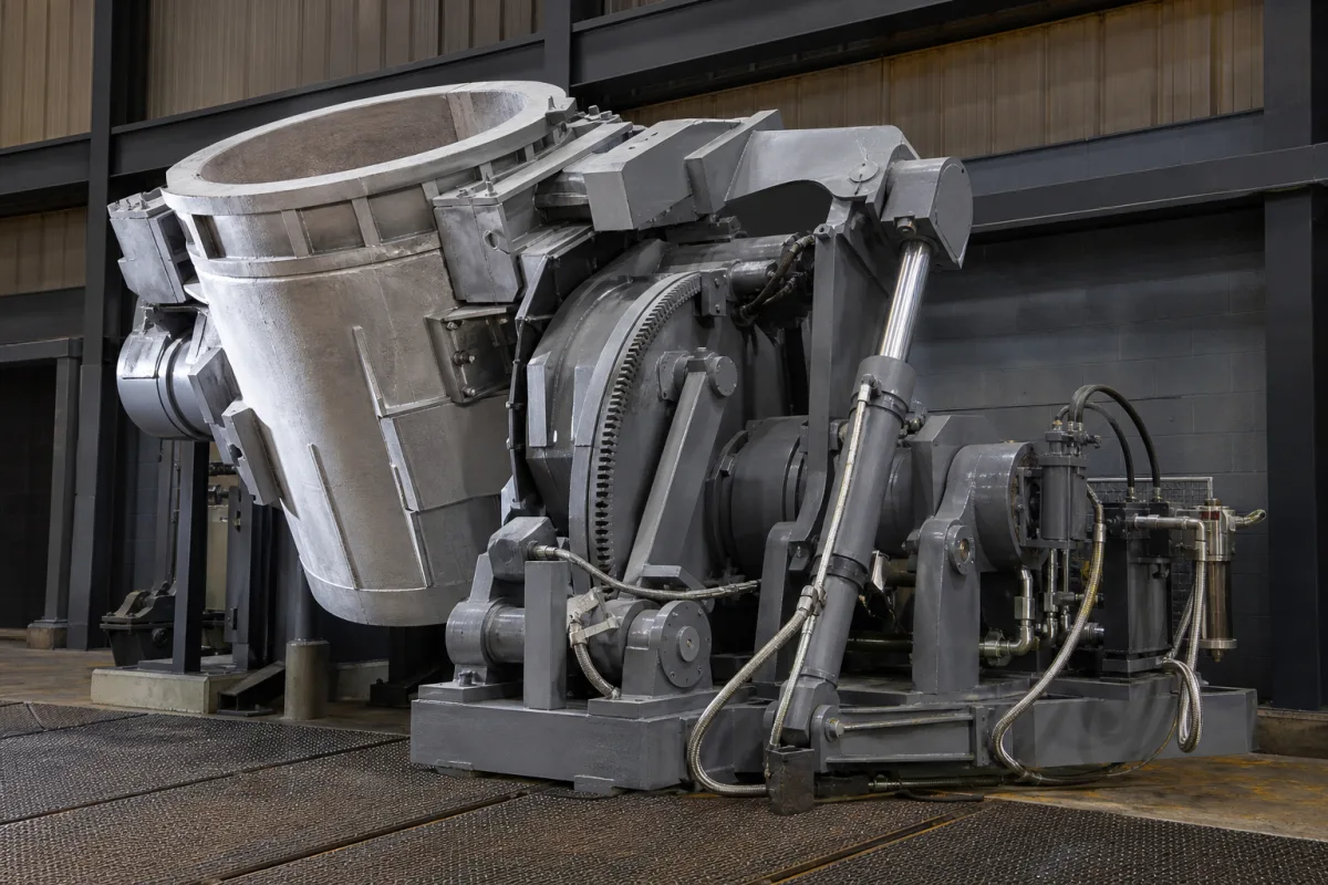
Geared tilting mechanism for ladles, crucibles and pouring furnaces: worm-and-wheel gearboxes, rack-and-pinion drives on the tilt shaft, and the locks and bearings that carry the vessel
Foundry and steel plant · the gear train that turns a ladle, crucible or furnace about its tilt shaft: worm-and-wheel gearboxes, rack and pinion, gear rings, with the lock that holds the vessel still
A pouring vessel does not tip itself at a controlled rate. Something has to turn it about its trunnions or tilt shaft, hold it at any angle while metal is running, and stop it from running away when the load moves past the pivot. This page is about the geared answer to that: a worm gearbox with a hand wheel or motor on a crane-carried ladle, a rack driven by a cylinder against a pinion on a crucible shaft, or a large gear on a ladle cradle, together with the locks, bearings and position switches that go with them.
Geared tilt drives for molten-metal vessels: worm-and-wheel gearboxes with hand wheel or motor on lip-pouring and bottom-pour ladles, rack-and-pinion and gear-ring drives that turn the tilt shaft of crucibles, ladle cradles and furnace bodies, and their locks, trunnion bearings and position switches. Cylinder-driven tilting frames with counterbalance valves and hydraulic power units are covered on the Hydraulic ladle tilting mechanism (cylinder-driven pouring unit) page; the furnaces themselves on the Induction melting furnace and Non-ferrous metal induction melting furnace pages; converter tilt drives on the Basic oxygen furnace vessel page; robot-held and automatic pouring ladles on the Robotic pouring systems page; the ladle shell and lining on the Refractory-lined steel ladle page; slag removal from a tilted ladle on the Slag skimming machine page; and stand-alone angle sensors on the Control sensor page.
CNFX editorial research · Sources checked October 13, 2026 · 5 sources
Worm-and-wheel gearboxes on crane-carried ladles: Ohio's 2,000 lb gear rule and a 15 t ladle specification
Ohio's metal-casting safety rule for ladles draws the line at which a lip-pouring ladle must be geared: tilting ladles exceeding two thousand pounds capacity shall be of the gear-operated type, and every mechanically or electrically operated tilting ladle shall have a locking device or brake to prevent overturning or uncontrolled sway. [1]
The same rule, effective 1 January 2025 with prior effective date 1 January 1981, also limits the refractory rim on hand or bull ladles to no more than one-half inch above the metal shell, or one inch where the lining is at least one and one-half inches thick at the rim. [1]
A tender by Bharat Heavy Electricals (BHEL) for a crane-suspended 15 t bottom-pouring steel ladle shows what a buyer writes into the gear part of such a ladle. [2] The tentative shell is 1,900 mm across the top, 1,700 mm at the bottom and 1,900 mm high, with 16 mm side and 20 mm bottom plate, and the ladle carries a lip on both sides so that it can pour to the left or right. [2]
Gear-train item in the BHEL 15 t ladle tender
What the tender asks for
Tilting arrangement
Worm and worm wheel, in an integrated gearbox, with a hand wheel for manual tilting [2]
Welded integral to the shell through trunnion pads and mounted on ball bearings [2]
Locks
Safety locks for both arms; a secondary locking assembly on the gearbox handle to lock the gearbox while the ladle is moved with the shell partly rotated; a lock against tilting while the ladle carries metal [2]
Protection
Splash guard over the rotating parts of the gearbox exposed to the atmosphere; a heat shield under the bail [2]
Stability
The ladle to remain stable at all angles and not move forward or backward under its own weight and the weight of the metal [2]
For a geared ladle, give the supplier the full metal capacity, the shell dimensions and trunnion height, whether the gearbox is hand-wheel or motor driven, the materials of the worm and wheel, and which locks must act during crane travel and during pouring.
02
Rack and pinion on the crucible shaft: the Leybold-Heraeus pressure roller that removes stick-slip from the pour
Where a set quantity of metal has to leave a crucible per unit time, the drive must turn the shaft at a steady angular velocity from the first degree of tilt to the end of teeming. A 1988 US patent assigned to Leybold-Heraeus describes how its earlier rack drives failed that test and how the patented drive fixes it. [3]
In the patent, the crucible hangs from a horizontal tilt shaft; a pinion on the shaft is engaged tangentially by a rack fixed directly to the piston rod of a hydraulic cylinder. [3] In the known designs the rack was pressed against the pinion by an adjustable slide shoe which, in the patent's words, "has a tendency to stick", so a jumpy movement of the rack could not be reliably prevented, and the fixed cylinder let the rack deflect slightly; the patent calls such mechanisms virtually unusable for controlled teeming. [3]
The patented drive replaces the slide shoe with a pressure roller journalled in an adjustable bearing mount, which holds the rack against the pinion without clearance, and hangs the cylinder from a boom on the same mount so that it can swivel about a pivot parallel to the tilt shaft. [3] Roller, rack, piston rod and cylinder then move together towards or away from the pinion, so the rack and rod are not bent. [3] On a vacuum casting chamber, a hermetic lead-through in the chamber wall serves at the same time as the pivot bearing of the tilt shaft, and a cam on the free end of the rack works a limit switch for position indication. [3]
For a rack or gear-ring drive, ask how backlash between rack and pinion is taken up, how the cylinder or motor is mounted relative to the gear, how the angle is measured, and what angular speed range the control holds during pouring.
03
Where the gear load peaks: a 200 t ladle cradle, and a centre of gravity kept behind the tilt axis
SGS Sonder Getriebe Service reported in 2010 that it had supplied a combined worm-spur gear unit for a new ladle tilting cradle at Dillinger Hüttenwerke, the device that tilts the ladle into a horizontal position. [4]
SGS states that the gearing was laid out to carry temporarily seven times the nominal load, because of the impact loads during tilting, and that all load-carrying parts were analysed and optimised by finite element analysis. [4] According to SGS, the impact loads travel from the output shaft through the whole gear system and are highest when the 200 t ladle is tilted back from horizontal to vertical, when its full weight presses into the pivot points of the cradle; a torsion shaft device absorbs these loads. [4]
The geometry of the cradle decides which way the load acts on the drive. In a 1979 US patent for a hot metal ladle tilter assigned to The William B. Pollock Company, a ladle weighing 275 tons full, about 15 ft across and 15 ft high, sits on a support frame pivoted in spherical bearings. [5] The ladle is tilted to about 60° from vertical with the minimum charge of about 237,000 lb, 47.5° with 420,000 lb and 39° with the maximum of about 510,000 lb, and at each of these positions the combined centre of gravity of ladle, metal and frame stays behind the vertical plane through the tilt axis. [5] As a result, on a failure of the hydraulic or electrical supply the frame and ladle return upright by gravity, at a rate set by orifice valves, and stop brackets with a cushioning and insulating sheet limit the rearward swing. [5]
Editorial calculation from the Pollock figures: 237,000 lb is about 107.5 t, 420,000 lb about 190.5 t and 510,000 lb about 231.3 t of metal; adding about 273,000 lb (about 124 t) of charge reduces the tilt needed by 21°, from 60° to 39°. [5]
Ask the drive supplier for the torque at the worst angle and the design overload factor, which way the vessel moves if the drive or its supply fails, how far the centre of gravity can move past the tilt axis with the heaviest charge, and what limits the stroke at both ends.
04
What a geared tilt drive enquiry should state
Paste it into your enquiry below or into an email to a maker, then replace every bracket.
Vessel: [ladle, crucible or furnace; full mass with metal; empty mass]
Geometry: [trunnion or tilt-shaft position; centre of gravity full and empty; tilt range each side]
Drive: [worm gearbox with hand wheel or motor; rack and pinion with cylinder; gear ring with motor]
Gearing: [worm and wheel materials; ratio; design overload factor]
Holding: [locks during crane travel; brake or lock during pouring; behaviour on power failure]
Control: [angular speed while pouring; position switch or angle sensor]
Environment: [splash and heat protection; vacuum or air]
Explore company information and manufacturing capabilities, then discuss the scope of your project with a relevant supplier.
Share this page
Compiled and source-reviewed by the CNFX editorial team.
Each manufacturer above links to the page on that company's own website where the product is listed, with the date we checked it. How we source and review
· Page last updated 13 October 2026
Buyer questions
When does a tilting ladle have to be gear-operated?
Ohio's metal-casting rule requires tilting ladles exceeding 2,000 lb capacity to be gear-operated, and mechanically or electrically operated tilting ladles to have a locking device or brake. [1]
What materials does a ladle worm gearbox use?
A BHEL tender for a 15 t steel ladle asks for a steel gearbox body, a phosphor-bronze worm wheel, and worm shaft and bevel gears in EN-8 bar. [2]
Why can a rack drive make a crucible pour unevenly?
A Leybold-Heraeus patent says the slide shoe that pressed the rack against the pinion in known designs "has a tendency to stick", so jumpy rack movement could not be reliably prevented; it replaces the shoe with a pressure roller in an adjustable mount. [3]
When is the load on a ladle tilt gear highest?
SGS says the highest loads on its Dillinger cradle gear occur when the 200 t ladle is tilted back from horizontal to vertical; the gearing was laid out for seven times the nominal load. [4]
What happens to a tilted ladle if the drive loses power?
In the Pollock ladle tilter patent the combined centre of gravity stays behind the tilt axis at every pouring position, so the ladle returns upright by gravity at a rate set by orifice valves. [5]
Sources and what still needs a direct check
Sources checked 2026-10-13. The Ohio rule is a state safety regulation for metal casting; the BHEL document is a buyer's tender specification for a 15 t ladle; the Leybold-Heraeus and William B. Pollock documents are US patents describing their own tilt drives; the SGS item is the gear maker's own announcement, published on bulk-online.