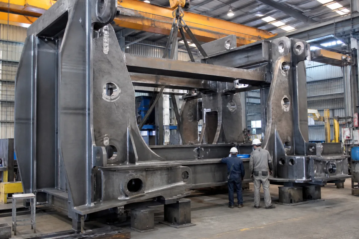
Welded frame structure of a plate rolling machine: box-section side frames, the chassis that ties them, and stress relief before the roll bores are machined
Plate rolling machine weldments · box-section side frames and chassis, frame size steps across a model range, stress relief before machining the roll bores
Every roll of a plate rolling machine runs in bearings held by two upright side frames, and the bending force on the plate comes back into those frames and the chassis that joins them. The frame structure is built as a steel weldment: thick plates cut, welded into box-shaped housings, joined by a base and cross members, stress relieved and then machined so that the roll bores line up. Whether the rolls stay parallel under load, and whether they stay parallel after years of heavy work, depends on how this weldment was designed, heat treated and machined.
The welded side frames (housings), chassis or base, cross members and tie beams of three- and four-roll plate rolling machines: box-section construction, frame size steps across a model range, stress relief after welding, machining of the roll and cylinder bores, and the drop-end side that opens to release a closed cylinder. Roll configurations, capacities and complete-machine selection are covered on the Plate rolling machine page; the lower (pinch) roll itself, its deflection, crowning and drive, on the Bottom (lower pinch) roll of a plate rolling machine page; portal clamping frames that hold a welded machine base during welding on the Hydraulic clamping frame for heavy weldments page.
CNFX editorial research · Sources checked October 13, 2026 · 3 sources
Box-section side frames tied by a box chassis rather than H or U beams
Anerka, a Turkish plate roll maker, states in its brochure that the precision of a roll bending machine depends on the robustness of its frames and chassis. It builds the side frames as box constructions from heavy metal plates and connects them through a box-design chassis, which it says resists torsional moments far better than frames sitting on a simple H- or U-beam base. [1]
Durma describes the same concern for its HRB three-roll machines: the body is strengthened and lowered to minimise twisting and deformation. Durma also says HRB machines bend to a minimum diameter of 1.5 times the top roll diameter, against 3 times that it gives for other machines on the market. [2] Anerka quotes 1.1 times the top roll diameter for cylinders on its HRR-4 series, which it credits to rectilinear roll guides, and 1.5 times for cones, which it links to heavy frames and angled bottom and side rolls. [1]
Ask for the frame drawing or a section through the side frames and chassis: plate thicknesses, whether the chassis is a closed box or open beams, and how the side frames are joined to it.
02
Three frame sizes across one three-roll range: width, height and mass
Anerka's HR-3 hydraulic three-roll table shows how a maker carries a model range on a few frame sizes. Machines with 200 to 230 mm top rolls share an overall width of 1,160 mm and height of 1,180 mm, those with 270 to 330 mm rolls 1,660 mm and 1,590 mm, and those with 360 to 430 mm rolls 2,060 mm and 2,050 mm. The table states that its capacities hold for plate of 260 N/mm². [1]
Editorial calculation: within the 1,660 mm frame size, going from the 270 mm to the 330 mm roll adds 1,570 kg (about 19 %); stepping from the 230 mm machine to the 270 mm machine, where the frame size changes, adds 3,480 kg (about 73 %), and from 330 to 360 mm adds 5,050 kg (about 51 %). These are whole-machine masses, including rolls, drives and hydraulics, so they show where the frame steps fall in the range rather than the frame mass itself. Anerka notes that mass and motor power may increase with optional features. [1]
Editorial note: when two models share a frame size, the smaller-roll model shares its overall frame dimensions with the larger-roll model; when a model sits at the top of its frame size, ask how much margin the frame has at full rated capacity, pre-bending included.
Stress relief at 600–675 °C after welding, then machining every bore from one reference
Anerka states that its frames and chassis are stress relieved after welding and that the whole body is then machined on 5-axis CNC machining centres from a single fixed reference point, which it says gives parallel axes and precise surfaces that keep the machine's critical characteristics over its life. [1] Durma says the frame and steel bar connections of its HRB machines are stress relieved after the welding operation. [2]
Total Materia's article on stress relief of steels says carbon steels are stress relieved by holding at 600 to 675 °C (1,100 to 1,250 °F) for 1 hour per 25 mm of thickness, which gives greater dimensional stability during machining. [3] Editorial calculation: on that rule, a side frame whose thickest plate is 100 mm would be held for about 4 hours at temperature, plus the heating and cooling time of a weldment of that mass.
Editorial note: the order matters. Stresses locked in by welding and flame cutting are released when material is removed, so a frame machined before it is stress relieved can move after the bores are cut. Ask the maker for the stress relief record (temperature, hold time and furnace or method) and whether bores and mounting faces were machined after it, in one setup.
Ask for the stress relief chart or certificate for the frame weldment and the machining sequence: which faces and bores were cut after stress relief and from which datum.
04
The drop-end side frame and where the snubber is mounted
On Anerka's HR-4 four-roll machines a hydraulic drop end lets formed pieces be removed, with a cone snubber on the top roll bearing that rotates out of the way; on its HRR-4 series a heavy roller snubber is mounted to the main frame and the top roll is tilted up hydraulically for removal. [1]
Editorial note: on a drop-end machine one side frame is split, with a hinged or tilting bearing housing that has to carry the full top-roll reaction when closed and swing clear when open. Ask how the drop-end housing locks to the frame, what holds the top roll while it is open, and whether the frame was machined with the drop end fitted.
05
Frame details to ask a plate roll maker for
Paste it into your enquiry below or into an email to a maker, then replace every bracket.
Machine: [three- or four-roll; bending length; top roll Ø; capacity at stated yield]
Side frames: [box or single-plate; plate thicknesses; steel grade]
Chassis: [box chassis or beams; how frames are joined]
Stress relief: [method; temperature; hold time; certificate]
Machining: [bores and faces machined after stress relief; single setup; datum]
Drop end: [hinged or tilting housing; locking; top-roll support when open]
Mass: [machine mass; frame mass if available]
Explore company information and manufacturing capabilities, then discuss the scope of your project with a relevant supplier.
Share this page
Compiled and source-reviewed by the CNFX editorial team.
Each manufacturer above links to the page on that company's own website where the product is listed, with the date we checked it. How we source and review
· Page last updated 13 October 2026
Buyer questions
Why are plate roll side frames built as boxes?
Anerka builds its side frames as box constructions from heavy plates joined by a box chassis, which it says resists torsion better than a simple H- or U-beam base. [1]
Is the frame stress relieved?
Anerka and Durma both say their frames are stress relieved after welding; Anerka then machines the whole body from one reference. [1][2]
At what temperature is carbon steel stress relieved?
Total Materia gives 600 to 675 °C for 1 hour per 25 mm of thickness. [3]
How heavy is a plate rolling machine?
In Anerka's HR-3 range at 3,100 mm length, from 4,500 kg with a 210 mm top roll to 17,700 kg with a 430 mm top roll. [1]
Sources and what still needs a direct check
Sources checked 2026-10-13. Anerka's plate roll brochure (frame construction, stress relief and HR-3 and HR-4 tables), Acra Machinery's listing of Durma HRB three-roll machines, and Total Materia's article on stress relief of steels.