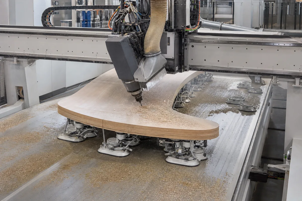
5-axis CNC wood router on a bar-and-suction-cup console table: holding curved and edge-machined parts clear of the bed
Five-axis routing on a console table rather than a flat bed · bars and suction cups that hold a part up off the table, how their positions are set and checked, and what a vacuum cup actually holds
A five-axis head can approach a part from the side and below the top face, which a part lying flat on a full vacuum bed blocks. Console machines solve this by carrying the workpiece on suction cups or clamps mounted on bars that slide along the machine, so the part sits raised with open space around its edges. The price is set-up: every bar and cup has to be in the place the program expects, each cup holds only the area under it, and a curved part needs cups that can follow its shape. These are the points that separate one console-table five-axis router from another.
Five-axis CNC routers and machining centres for wood and wood-based panels that hold the workpiece on vacuum suction cups or clamps mounted on movable bars (console or pod-and-bar tables), including manual, measured and motor-positioned bar systems and tilting suction cups for curved parts. Flat-bed three-axis panel routers, their tooling and cutting feeds are covered on the CNC wood router page. Grid vacuum tables for nesting are outside this page.
CNFX editorial research · Sources checked October 12, 2026 · 3 sources
Bars and cups instead of a flat bed: manual, measured and motor-positioned console tables
SCM Group's patent application EP3696631A1 describes the work surface of these machining centres: bars that slide along the base, each carrying suction cups or clamps that slide along the bar, with vacuum supplied through channels in the bars, and an operating unit whose machining unit can have up to 5 interpolating axes. [1] On a surface with manual bars, up to six suction cups can be mounted on each bar, removed and freely repositioned for the part being machined. [1]
In SCM's coded scheme each bit corresponds to 1 mm, so an 11-bit sequence codes positions from 0 to 2,048 mm along a bar and a 15-bit sequence codes 32,768 mm; the control unit compares the stored work-surface configuration with the positions read and emits signals on the result. [1] Editorial calculation: at 1 mm per bit, 2¹¹ = 2,048 positions cover a 2,048 mm bar, which is why the example uses 11 bits per bar and longer sequences along the machine base.
Bar-and-cup system
How positions are set
Drawback stated in EP3696631A1
Manual
Operator places bars along the base and cups along each bar
No information to the operator on whether the positioning is correct [1]
Semiautomatic
Placed by hand, with magnetic or magnetostrictive linear measuring lines giving feedback
Significant, bulky wiring for the measuring systems [1]
Automatic
Bars motor-driven on a rack; cups moved one at a time by a carriage on a belt, or by a motor on a rack
High cost and large overall dimensions of motors and carriages [1]
Manual with coded measuring (the patent's proposal)
Placed by hand; optical sensors read binary codes on the base and the bars and the control compares them with the stored configuration
Editorial note: ask which of the four set-up methods the machine uses and whether the program checks the bar and cup positions before the spindle starts.
02
What a vacuum-clamped panel holds: −0.9 bar, 85% pull-off efficiency on chipboard and 75% on MDF
Csanády and Németh at the Technical University in Zvolen measured vacuum clamping on a CNC router's raster table, where rubber profiles in a chequered groove pattern bound the vacuum area. Their pump could reach −0.9 bar, and they write the hold-down force as vacuum pressure times area; a part stays put as long as cutting forces stay below the static friction force. [2] Their tests were on a flat raster table rather than on console cups, but the physics of a sealed vacuum area under a panel is the same question a console buyer asks of each cup.
The authors conclude that the area sealed off on the table should not be regarded as a 100% effective vacuum area. [2] Editorial calculation: at −0.7 bar on the 0.0656 m² specimen used in their sliding tests, the theoretical hold-down is 70,000 Pa × 0.0656 m² ≈ 4.6 kN; at the 85% efficiency they report for chipboard pull-off, about 3.9 kN would remain.
Their three-component force measurements on oak, beech or birch and MDF showed a Z-direction force of variable amplitude even with a straight cutter, which they attribute to the heterogeneous structure of wood, and a slanted cutter reduced the Y-direction force on the clamping while increasing the Z-direction force. [2]
Test in the Zvolen study
Result reported
Pull-off of panels up to 400 × 400 mm, areas 0.0458–0.1235 m²
Clamping force fell almost linearly with falling vacuum [2]
Curved and sloping parts: swinging suction cups on a spherical head
C.M.S.'s patent application EP2087964 starts from the case a five-axis router meets with curved work: flat items sit on coplanar cups, but curved elements that have to be cut out, profiled and machined on multi-axis machine tools need supports that follow their shape. [3] Its answer mounts each suction cup on a cover connected to a spherical head, adjustable in height and movable in all directions between a horizontal and a sloping position, with a control device to set the horizontal position and a pulling device that changes the tilt when an outside force is applied. [3]
The application lists composite material, wood, glass and marble among the materials such tables hold, and describes the aim as a universal fixture that adapts to the curvature of each item and to size differences between items of the same model. [3] For a buyer, that means stating whether the parts are flat panels, curved laminated parts or solid shaped components before the console layout and cup types are quoted.
04
Data for a five-axis console router enquiry
Paste it into your enquiry below or into an email to a maker, then replace every bracket.
Parts: [flat panels, curved laminated parts or solid shapes; largest and smallest part; thickness]
Machining: [edge profiling, undercuts, drilling at angles; materials]
Table: [number of bars; cups per bar; cup heights; clamps for small parts]
Set-up: [manual, measured or motor-positioned bars and cups; position check before start]
Vacuum: [pump capacity; separate vacuum circuits; tilting cups for curved parts]
Head: [tilt and rotation ranges; spindle power and tool interface]
Explore company information and manufacturing capabilities, then discuss the scope of your project with a relevant supplier.
Share this page
Compiled and source-reviewed by the CNFX editorial team.
Each manufacturer above links to the page on that company's own website where the product is listed, with the date we checked it. How we source and review
· Page last updated 13 October 2026
Buyer questions
Why do five-axis wood routers use bars and suction cups instead of a flat vacuum bed?
The cups hold the part raised so the head can work around its edges. SCM's EP3696631A1 describes bars sliding along the base with up to six repositionable suction cups each, fed with vacuum through the bars. [1]
How is a wrongly placed cup avoided?
Manual tables give no feedback; semiautomatic tables use magnetic or magnetostrictive lines; automatic ones motor-drive bars and cups. SCM's proposal reads 1 mm-per-bit optical codes and compares them with the stored layout. [1]
Does a vacuum area hold its full theoretical force?
Not in the Zvolen tests: pull-off force started at 85% of theory on chipboard and 75% on MDF, and the authors say the sealed area should not be treated as 100% effective. [2]
How are curved parts held?
C.M.S.'s EP2087964 mounts each cup on a spherical head so it can tilt from horizontal to a sloping position and follow the part's curvature. [3]
Sources and what still needs a direct check
Sources checked 2026-10-12. Bar-and-cup layouts and position coding come from SCM Group's EP3696631A1; vacuum hold-down, pull-off efficiency and friction tests from Csanády and Németh's 2008 Zvolen conference paper; tilting cups for curved parts from C.M.S.'s EP2087964A2.