Editorial Technical Reference

Vision/Positioning Sensors

This page explains how Vision/Positioning Sensors is classified within Machinery and Equipment Manufacturing. Technical values and manufacturer relationships are research references; confirm the current specification and supplier evidence for each order.

Technical Definition & Core Assembly

Optical and electronic sensors that detect, identify, and track objects to guide robotic pouring operations.
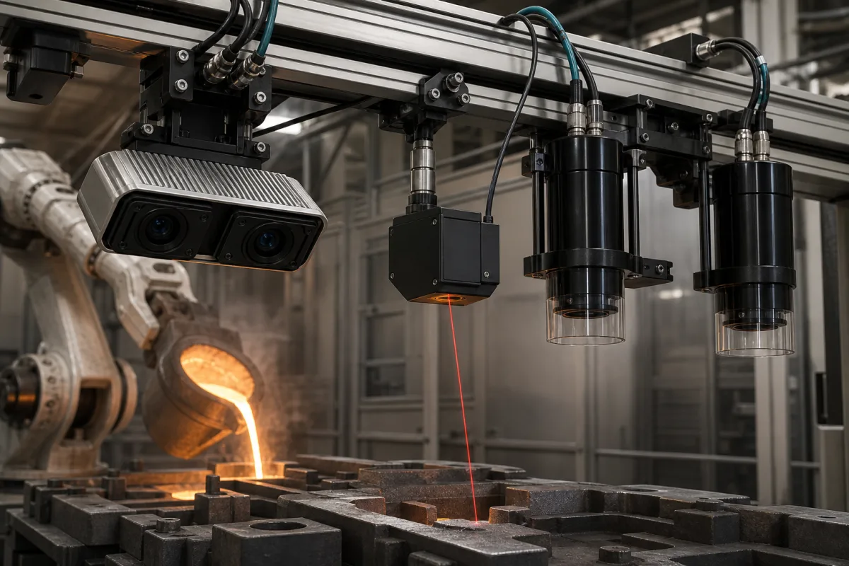
Representative product image. Confirm appearance and specifications with the manufacturer.

Product Specifications

Technical details and manufacturing context for Vision/Positioning Sensors

Definition
Vision/Positioning Sensors are critical components within a Robotic Pouring System that provide real-time visual feedback and spatial positioning data. They enable the robotic system to accurately identify target containers, measure fill levels, track pouring trajectories, and ensure precise material deposition. These sensors typically combine cameras, laser scanners, or other optical devices with processing algorithms to create a digital representation of the work environment, allowing for adaptive control of the pouring mechanism. The sensors are housed in corrosion-resistant aluminum or stainless steel enclosures, with optical glass for the lens and silicon-based sensing elements. They are designed for industrial environments, offering protection ratings from IP65 to IP67 per IEC 60529. Key parameters include a detection range of 0.1 to 5 meters, resolution of 0.1 to 1 mm, repeatability of ±0.05 mm, and response time of 1 to 10 ms. They operate on a 24 V DC supply (±10%) with current consumption between 50 and 200 mA, and provide PNP or NPN outputs for PLC compatibility. The operating temperature range is -10 to 50 °C, and the sensors weigh between 0.5 and 2 kg, with dimensions ranging from 50×30×20 mm to 100×60×40 mm. These sensors are essential for adaptive control, enabling the robotic system to adjust pouring parameters in real time based on visual and positional feedback. They are used in machinery and equipment manufacturing, particularly in automated pouring processes. For specific applications, it is crucial to verify model-specific values and standards with the legal manufacturer or supplier, as the listed parameters are reference ranges and may vary by model.
Working Principle
Vision sensors capture images of the target area using cameras, while positioning sensors (such as laser distance sensors or encoders) measure spatial coordinates. Image processing algorithms analyze the visual data to identify objects, edges, and features. Positioning data provides real-time location feedback. The combined data is processed by a control system to calculate precise pouring paths, monitor fill levels, and adjust robotic movements accordingly. The sensors output signals (PNP/NPN) that interface with PLCs or other controllers, enabling closed-loop control. The system's accuracy depends on proper calibration and environmental conditions, such as lighting and dust. Regular maintenance includes cleaning optical surfaces and checking alignment. Failure modes include sensor drift, signal loss, or physical damage, which can be detected through diagnostic outputs or periodic verification.
Common Materials
Optical glass, Aluminum alloy housing, Silicon sensors, Copper wiring
Technical Parameters
ParameterTypical rangeNotes & selection driver
Detection Range0.1–5 mWorking distance for reliable object detection
Resolution0.1–1 mmMinimum detectable object size
Repeatability±0.05 mmPositioning consistency for robotic guidance
Response Time1–10 msTime to output signal after detection
Supply Voltage24 ±10% V DCTypical industrial DC supply
Current Consumption50–200 mAAt nominal supply voltage
Output TypePNP/NPNConfigurable for PLC compatibility
Operating Temperature-10–50 °CAmbient temperature range
Protection RatingIP65–IP67Dust-tight and water-jet protectedIEC 60529
Housing MaterialAluminum/Stainless SteelCorrosion-resistant for industrial environments
Weight0.5–2 kgDepends on housing and optics
Dimensions (L×W×H)50×30×20 – 100×60×40 mmCompact design for easy integration

Ranges are indicative industry figures for RFQ preparation, not a supplier commitment. Confirm every value and standard with the legal manufacturer before ordering.

Components / BOM
  • Image Sensor
    Converts optical images into electronic signals for processing
    Material: Silicon
  • Lens Assembly
    Focuses light onto the image sensor with appropriate field of view
    Material: Optical glass
  • Processing Unit
    Analyzes image data and calculates positioning information
    Material: Semiconductor materials
  • Housing Part
    Protects internal components from environmental factors
    Material: Aluminum alloy
  • Laser Distance Sensor or Encoder
    Measures spatial coordinates — the positioning half of the product.

Industry Taxonomies & Aliases

Commonly used trade names and technical identifiers for Vision/Positioning Sensors.

Applied To / Applications

This component is essential for the following industrial systems and equipment:

Industrial Ecosystem & Supply Chain Structure

Complementary Systems
Downstream Applications
Specialized Tooling

Application Fit & Sizing Matrix

Operational Limits
pressure: Atmospheric (non-pressurized environment)
other spec: Object detection range: 0.1m to 10m, Accuracy: ±0.5mm, Response time: <10ms, IP67 rating
temperature: -10°C to +50°C (operating), -20°C to +70°C (storage)
Media Compatibility
✓ Molten metals (aluminum, steel) ✓ Concrete slurry ✓ Polymer resins
Unsuitable: High-density fog or steam environments (optical interference)
Sizing Data Required
  • Maximum pouring distance (m)
  • Target object size and shape (mm)
  • Required positioning accuracy (mm)

Reliability & Engineering Risk Analysis

Failure Mode & Root Cause
Optical contamination
Cause: Accumulation of dust, oil mist, or debris on lens surfaces, blocking or scattering light, often due to inadequate environmental sealing or improper cleaning practices.
Laser/LED degradation
Cause: Gradual output power reduction or wavelength shift from thermal stress, aging, or electrical overstress, leading to unreliable signal detection.
Maintenance Indicators
  • Intermittent or erratic position readings during stable conditions
  • Visible condensation, residue, or physical damage on the sensor lens or housing
Engineering Tips
  • Implement regular, gentle cleaning of optical surfaces using approved, non-abrasive materials and solvents, avoiding mechanical stress on delicate components.
  • Ensure stable, clean power supply with proper voltage regulation and surge protection to prevent electrical stress on internal electronics.

Indicative industry ranges for design and RFQ preparation. Confirm the exact figures and applicable standard with the manufacturer before specifying.

Compliance & Manufacturing Standards

Applicable Standards
ISO 9283:1998 - Performance criteria and testing for industrial robots ANSI/RIA R15.06-2012 - Industrial Robots and Robot Systems Safety Requirements CE Marking - Directive 2014/35/EU (Low Voltage Directive) and 2014/30/EU (EMC Directive)

Quoted from the published standard.

Manufacturing Precision
  • Positioning Accuracy: +/-0.01mm
  • Repeatability: +/-0.005mm
Quality Inspection
  • Environmental Testing (IP Rating Verification)
  • Calibration Verification with Certified Reference Standards

Manufacturers of Vision/Positioning Sensors

Manufacturer profiles associated with Vision/Positioning Sensors.

Sourcing Vision/Positioning Sensors from China?
Tell us your specification and target quantity — we will match it against manufacturer records and come back with the factories that fit.
Request manufacturers We manufacture this

Manufacturer listings support early research and capability understanding. They are not certification, ranking, or transaction guarantees.

Technical documentation
Request current drawings, revision history, and a signed specification sheet.
Manufacturing capability
Verify equipment lists, process limits, capacity, and representative production evidence.
Inspection readiness
Confirm test methods, calibrated equipment, sampling plans, and traceable reports.
Supplier transparency
Check the legal entity, factory address, ownership, certifications, and direct contacts.

CNFX does not score or rank suppliers. Buyers must verify all claims and documents with the legal manufacturer before ordering.

Supply Chain Compatible Machinery & Devices

Hydraulic Press

Industrial machine using hydraulic pressure to compress, form, or assemble materials

Explore Specs →
Heavy-Duty CNC Plasma Cutting Machine

The Heavy-Duty CNC Plasma Cutting Machine is a standalone industrial device designed for cutting conductive metals such as steel, stainless steel, aluminum, and copper alloys.

Explore Specs →
Automated Powder Coating System

Integrated industrial system for applying dry powder coatings to metal substrates.

Explore Specs →
Centrifugal Pump Impeller

The centrifugal pump impeller is a critical rotating component that converts mechanical energy from the motor into kinetic energy in fluid systems.

Explore Specs →

Frequently Asked Questions

What is the typical detection range of these sensors?

The detection range is typically 0.1 to 5 meters, but the exact range depends on the specific model and application. Always verify with the manufacturer.

What output types are available?

The sensors offer PNP or NPN outputs, which are configurable for PLC compatibility. The specific output type must be selected based on the control system requirements.

What is the operating temperature range?

The sensors operate in ambient temperatures from -10°C to 50°C. For extreme environments, consult the manufacturer for suitability.

What protection rating do these sensors have?

The protection rating is IP65 to IP67 per IEC 60529, meaning they are dust-tight and protected against water jets. However, actual rating may vary by model.

Data Basis

Editorial classification, named public sources where available, and source-reviewed manufacturer records.

Preliminary Technical Classification
This page supports structured research, RFQ preparation, and supplier evaluation. It does not replace buyer-led supplier qualification, standards review, or technical approval.
Buyer enquiry

Request manufacturing insight for Vision/Positioning Sensors

Ask for use case, specification boundaries, supplier type, and RFQ preparation information for this product.

Where it goes
Straight to the CNFX editorial desk, and to the manufacturer if this product is linked to a claimed profile. Nothing is broadcast to a supplier list.
Your details stay here
We do not sell or rent enquiry data, and we do not add you to a mailing list. Used only to answer this request.
No commission, no middleman
CNFX is a directory. We take no cut of any order and never negotiate on a supplier's behalf.
What we don't claim
A listing is not an endorsement. Qualify every supplier and verify every figure yourself before ordering.

Your business information is used only to process this request.

Thank you! Your message has been sent. We'll respond within 1–3 business days.
Sorry, we couldn't send your message. Please try again, or email us at contact@cnfx.com.

Need to Manufacture Vision/Positioning Sensors?

Compare manufacturer profiles with relevant product and process capability.

Previous Product
Z-axis Ram/Spindle
Last Product
Get QuotesChat