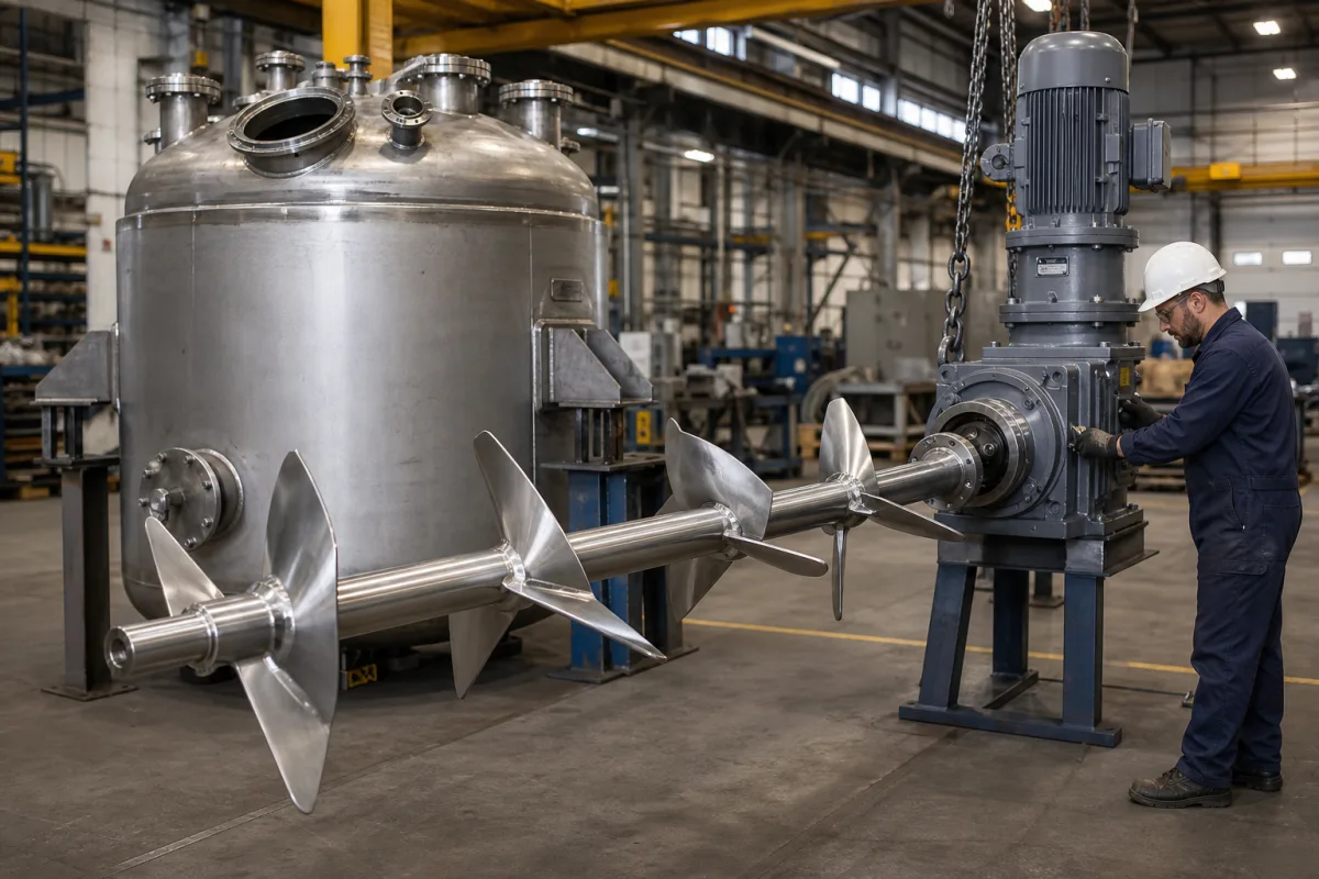
Agitator assembly (shaft train): the in-tank shaft, couplings, impeller stack and steady bearings sized against critical speed and deflection
The in-tank shaft train of a top-entry agitator · keeping the running speed below 0.4–0.8 of the first lateral critical, straightness to 0.25 mm per metre, coupled shaft sections, and steady bearings with loose clearances
Below the drive and seal of a top-entry agitator hangs the part that does the mixing and takes the punishment: a long shaft, in one piece or in coupled sections, carrying one or more impellers, and on tall vessels supported by steady bearings inside the tank. This assembly has to carry the torque and the bending loads from uneven flow, stay straight enough for the seal, and run clear of its own natural frequency in every operating state from full tank to draw-off.
The wetted shaft train of top-entry and column agitators: extension shafts in one piece or coupled sections, rigid in-tank couplings, impeller hubs and keyways along a multi-impeller shaft, and in-tank steady bearings, as designed for critical speed, bending deflection and runout. Impeller types and their power draw are covered on the Chemical reactor agitator blade (agitator impeller) page and curved paddles on the Curved paddle agitators page. The gear unit, output bearings and drywell above the vessel are covered on the Agitator head assembly page, packed stuffing boxes on the Chemical reactor sealing gland page, and complete hygienic food-tank agitators on the Top-entry hygienic agitator for food mixing tanks page.
CNFX editorial research · Sources checked October 13, 2026 · 3 sources
Running speed held at 0.4 to 0.8 of the shaft's first lateral critical speed
Andrew Creathorn of Lightnin Mixers, writing in the 2003 Pump Users Symposium proceedings, explains that mixers are operated subcritical, restricted to below a range of 0.4 to 0.80 times the first bending critical speed, with the exact ratio set by experience of the conditions the mixer will meet: asymmetric open flow fields, sparged gas, varying liquid level including an empty vessel, and draw-off with the impeller at the liquid surface, where fluid damping is essentially zero. [1]
Where the mounting can be treated as infinitely stiff, the paper takes a shaft speed at or below 80 percent of the calculated first natural lateral frequency as safe operation, and calculates that frequency with simple numerical methods. It lists the forcing frequencies with the highest energy as shaft speed, blade passing (shaft speed times the number of blades), baffle passing and motor speed. [1]
David Dickey, writing in Chemical Processing, names what sets that natural frequency: shaft length, shaft and impeller weights and the elastic modulus of the shaft material, with a complete calculation needing each impeller's weight, its distance from the support bearings and the bearing spacing. He advises leaving the calculation to the manufacturer but says the user must know the natural frequency, because variable frequency drives can be over-speeded towards it; he reports a 6 in stainless steel shaft bent until it struck an obstruction in the tank. [3]
Editorial calculation: for an agitator running at 100 rpm, the 0.80 ratio requires a first critical speed of at least 125 rpm (100 ÷ 0.80), and the 0.4 end of the range at least 250 rpm (100 ÷ 0.4). A four-blade impeller at 100 rpm has a blade-passing frequency of 400 per minute, about 6.7 Hz. [1]
Ask for the calculated first lateral critical speed of the shaft train with all impellers fitted, the ratio at maximum VFD speed, and which operating states (empty, draw-off, gassed) the ratio was chosen for.
02
An 88 ft, 9 in shaft at 1,000 hp: when the overhung shaft needs support
Creathorn's case was a six-stage agitated column 90 ft long, with one radial impeller per stage, an 88 ft shaft turning at over 100 rpm and transmitting 1,000 hp; the vessel was designed for 400 °F and 150 psi with a double mechanical seal. Even at the resulting 9 in diameter, the natural frequency and the overhung bending loads meant the shaft needed support in two places by steady bearings. [1]
The flow loads from the open flow field and sparged gas were treated as acting at each impeller centreline, perpendicular to the shaft; on a long overhung shaft the resulting bending moments would have caused excessive deflection, bent shafts and seal damage. Finite element analysis of the mixer and vessel together showed the first system mode (vessel rocking) below shaft speed, so with a variable speed drive a speed block-out range was specified; torsional frequencies were also checked against the forcing frequencies. [1]
On tall vessels or variable speed duty, ask whether the critical speed was calculated for the shaft alone or for the shaft, vessel and support structure together, and for any blocked speed ranges.
03
Steady bearings: plain bushings with L/D of 0.25 to 2.00 and deliberately loose clearance
In the same paper, steady bearings are plain bearings inside the vessel that stabilise long in-tank shafts; at mixer speeds no liquid film forms between bushing and sleeve, so they are not true journal bearings. [1]
Editorial calculation: on the 9 in shaft of Creathorn's case, 0.002–0.007 in per inch gives a diametral clearance of about 0.018–0.063 in (0.46–1.6 mm). [1] The paper warns that without this clearance the parts bind and fail early, and that start-up clearances must be calculated so that the running clearance is correct after thermal growth; in its design the wear sleeve had two running positions, doubling its life. [1]
Steady bearing feature
Published value
Length-to-diameter ratio
0.25 to 2.00; L/D 1.00 in high-temperature, long-life and aggressive services [1]
Shaft sections, rigid couplings, keyways and straightness
Chemineer's HT agitator brochure states that its shafts are sized for torsional loads and for bending moments from hydraulic forces on the impeller, and to avoid vibration from coincidence of critical frequencies with operating speed. Shafting is straightened to less than 0.003 in total runout per foot of length (0.25 mm per metre), supplied in one piece or in rigidly coupled sections, and for large diameters as pipe shafting with couplings and impeller hubs welded on. [2]
Extension shafts are joined to the drive shaft with flanged rigid couplings, either removable tapered-bore halves or welded halves, so the shaft need not be passed through the gearbox; in-tank couplings ease installation of long shafts, and extended keyways let the impeller position be changed. During a seal change on this design, the extension shaft drops less than 0.5 in onto a catcher bracket in the mounting flange, which carries the shaft and impeller weight. [2]
Editorial calculation: at 0.25 mm per metre, a 3 m extension shaft may show up to about 0.75 mm total runout along its length under that tolerance. [2] Ask how runout is measured on coupled sections after assembly, since each coupling face adds to it.
Specify shaft material and diameter, number and position of sections and couplings, impeller positions and adjustment range, runout tolerance and how it is checked, and the support for the shaft during seal changes.
05
Vessel, impeller and speed data for an agitator shaft train
Paste it into your enquiry below or into an email to a maker, then replace every bracket.
Vessel: [height; liquid levels including draw-off; pressure; temperature]
Duty: [power; speed range; VFD maximum; gassed or ungassed]
Impellers: [type; number; weights; positions on the shaft]
Shaft: [material; diameter; sections and couplings; runout tolerance]
Support: [steady bearings; bushing material; clearance; L/D]
Analysis: [first lateral critical speed; ratio at maximum speed; torsional check; blocked speed ranges]
Explore company information and manufacturing capabilities, then discuss the scope of your project with a relevant supplier.
Share this page
Compiled and source-reviewed by the CNFX editorial team.
Each manufacturer above links to the page on that company's own website where the product is listed, with the date we checked it. How we source and review
· Page last updated 13 October 2026
Buyer questions
How close to its critical speed can an agitator shaft run?
Lightnin's Creathorn gives operation below 0.4 to 0.80 times the first bending critical speed, chosen by duty; at most 80% where the mounting is effectively rigid. [1]
What sets the natural frequency of a mixer shaft?
Shaft length, shaft and impeller weights, the shaft material's elastic modulus, and the positions of impellers and support bearings, according to Dickey. [3]
How much clearance does a steady bearing need?
About 0.002 to 0.007 in per inch of shaft diameter, looser than a journal bearing because of shaft slope through the bushing. [1]
How straight is an agitator shaft made?
Chemineer states less than 0.003 in total runout per foot (0.25 mm per metre). [2]
Sources and what still needs a direct check
Sources checked 2026-10-13. A Lightnin Mixers engineer's paper in the Pump Users Symposium proceedings, Chemineer's HT agitator brochure (NOV), and an article on mixer mechanical design by David Dickey in Chemical Processing.