Feedback interface for CNC axes: encoder interface modules that interpolate 1 Vpp signals and read EnDat or SSI positions for the drive
Encoder-to-control electronics on CNC axes · 1 Vpp sine/cosine interpolation, EnDat and SSI clocking, amplitude monitoring and encoder cable limits
A CNC axis knows where it is only through its encoder, and the encoder's raw output is not something the control can use directly: a linear scale or rotary encoder sends two analogue sine waves 90° apart, a reference pulse, or a serial position word that has to be clocked out. The feedback interface is the electronics that turns that into a position value on the drive or machine bus. Choosing one means matching the encoder's signal type, the frequency the axis will generate at full speed, the cable run and the bus the control expects.
Encoder feedback interface modules for CNC machine axes and spindles: sensor modules, interface boxes and bus terminals that take incremental 1 Vpp sine/cosine, TTL/HTL, EnDat or SSI encoder signals and pass interpolated position values to a drive or control bus. CNC controls for milling machines, machining centres and lathes as a whole are covered on the CNC controller page; five-axis RTCP control on the 5-axis CNC controller page; press-brake numerical controls on the CNC control system for press brakes page; machine-side PLC I/O boards on the CNC input/output module page; motor modules that drive the axis on the Axis control module page; IEPE vibration front ends on the Signal conditioning circuit page; and the encoders themselves on the Servo motor feedback encoder, Linear encoder and High-resolution rotary encoder pages.
CNFX editorial research · Sources checked October 13, 2026 · 4 sources
Interpolating 1 Vpp sine/cosine signals: amplitude window, cutoff frequency and steps per period
HEIDENHAIN's interface brochure defines the 1 Vpp signals the interface has to accept: two nearly sinusoidal signals A and B, 90° ±10° electrical apart, with an amplitude of 0.6 to 1.2 Vpp, 1 Vpp (typ.), measured differentially across a 120 Ω terminating resistor, plus a reference mark signal with a usable component of at least 0.2 V. The amplitude falls as frequency rises; the brochure's signal parameters hold for motion up to 20% of the encoder's –3 dB cutoff frequency, where 70% of the amplitude remains. [1]
The interface does not count the sine periods only; it divides each one. HEIDENHAIN states that for speed control interpolation factors above 1000 are used, so that usable data remain available at low shaft or traverse speeds. [1] Beckhoff's EL5021 EtherCAT terminal shows what that looks like in a product: it accepts one 1 Vpp encoder at input frequencies up to 250 kHz, supplies the encoder with 5 V, and outputs a 32-bit count made of up to 24 bits of whole periods and up to 13 bits of position within one sine period. [2] Editorial calculation: 13 bits is 2^13 = 8,192 steps per signal period.
The input frequency limit translates into an axis speed limit. Editorial calculation, using an assumed 2,048-period rotary encoder: 250,000 periods per second ÷ 2,048 periods per revolution ≈ 122 rev/s, about 7,300 rpm, before the EL5021's 250 kHz limit is reached. [2] Siemens' SME20 sensor module for 1 Vpp encoders evaluates up to 500 kHz, which on the same assumed encoder is about 244 rev/s. [4]
HEIDENHAIN's reference input circuit for the receiving side uses an operational amplifier with a gain of 3.48 and a –3 dB cutoff of about 450 kHz, or about 50 kHz with larger capacitors, a variant it says gives up bandwidth for better interference immunity. [1]
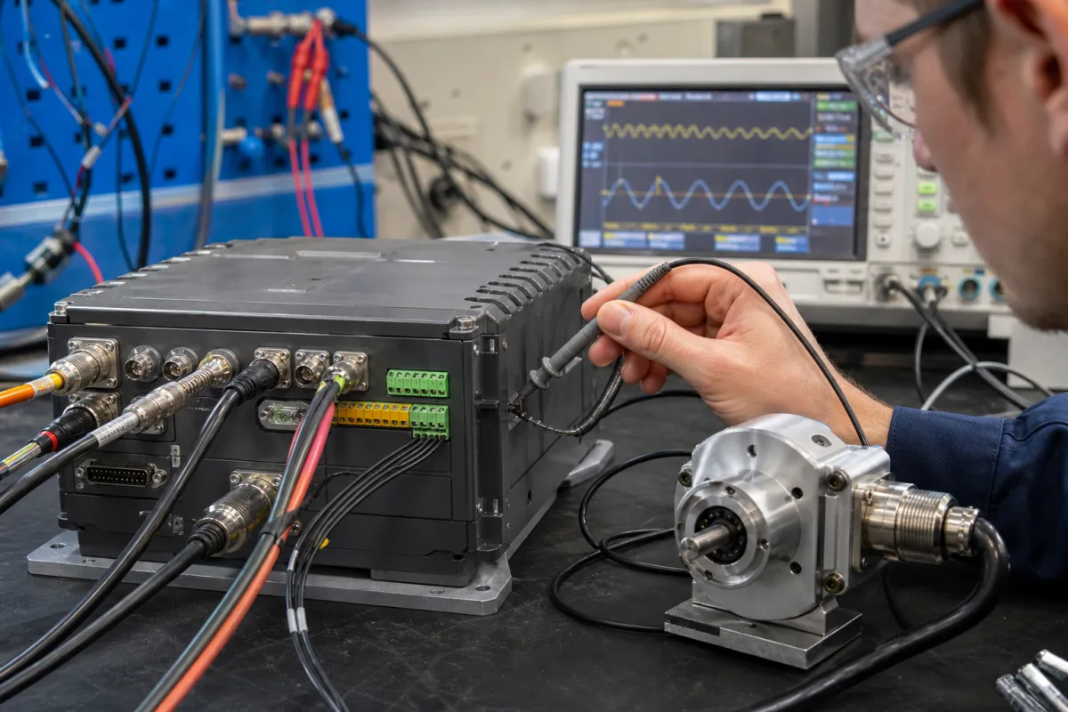
The image shows an interface box with circular encoder connectors, terminal blocks and a D-sub port on a bench, a rotary encoder beside it and two sine traces on an oscilloscope. Give the interface supplier the encoder's signal period or line count and the axis top speed, and ask at what input frequency the stated interpolation still holds.
02
Watching the signal: amplitude thresholds and error flags
HEIDENHAIN recommends that the downstream electronics monitor the 1 Vpp amplitude with a lower threshold of 0.30 Vpp and an upper threshold of 1.35 Vpp; on an oscilloscope in XY mode, A and B draw a Lissajous circle whose diameter is the amplitude. [1]
The EL5021 terminal reports amplitude errors and frequency errors of its input signals as diagnostics, and can latch or reset its counter on the encoder's reference mark (C track). [2]
HEIDENHAIN also warns that next to the reference mark the output can drop by up to 1.7 V to a quiescent value, and the receiving electronics must not be overdriven by this. [1]
03
Serial EnDat and SSI encoders: clock rate against cable length
With absolute encoders the interface acts as the master that clocks the position out. HEIDENHAIN gives the EnDat clock as variable between 100 kHz and 2 MHz depending on cable length, up to 150 m; with propagation-time compensation in the receiving electronics, clock frequencies up to 16 MHz or cables up to 100 m are possible, and the adapter cable at the encoder must not exceed 20 m. [1]
The Siemens manual (2008 edition) shows the split between module types: cabinet-mounted SMC10 for resolvers, SMC20 for 1 Vpp and EnDat 2.1, SMC30 for TTL/HTL, and external SME modules in IP67 for mounting outside the cabinet, each converting one encoder system to the DRIVE-CLiQ drive bus. [4] The EL5032 can synchronise its position read with other processes through EtherCAT distributed clocks. [3]
Cable length is limited differently by signal type: HEIDENHAIN allows up to 150 m for 1 Vpp cables with a signal propagation time of 6 ns/m, while Siemens limits the SME encoder cable to 10 m and ties the length to the encoder's current draw and the supply-conductor cross-section. [1][4] Editorial calculation: 150 m × 6 ns/m = 900 ns of one-way delay, the kind of delay propagation-time compensation exists to correct at high EnDat clock rates. [1]
Interface module
Encoder input
Published limits
Beckhoff EL5021 (EtherCAT terminal)
1 channel, sine/cosine 1 Vpp with reference mark
Up to 250 kHz input; 13-bit interpolation per period; 5 V encoder supply [2]
Beckhoff EL5032 (EtherCAT terminal)
2 channels, EnDat 2.2
Position value up to 48 bits depending on encoder; 5 V or optional 9 V encoder supply; reads the electronic nameplate and temperatures [3]
Siemens SME20 (sensor module, IP67)
Sine/cosine 1 Vpp
Up to 500 kHz; 5 V / 0.30 A encoder supply; encoder cable at most 10 m [4]
Siemens SME25 (sensor module, IP67)
EnDat 2.1 or SSI
Up to 500 kHz; SSI/EnDat 2.1 at 100 kHz baud rate; encoder cable at most 10 m [4]
04
What to tell the interface supplier about each axis
Position value and diagnostics have to reach the CNC [4][3]
05
Axis and encoder data for a feedback interface
Paste it into your enquiry below or into an email to a maker, then replace every bracket.
Axes: [number; linear or rotary; motor or direct measuring]
Encoder: [maker and model; 1 Vpp / TTL / HTL / EnDat / SSI / resolver; signal period or line count]
Speed: [maximum traverse or shaft speed]
Cable: [length encoder to module; adapter and extension]
Interface: [cabinet or IP67; supply voltage; bus to drive or CNC]
Diagnostics: [amplitude and frequency error reporting; reference mark handling]
Explore company information and manufacturing capabilities, then discuss the scope of your project with a relevant supplier.
Share this page
Compiled and source-reviewed by the CNFX editorial team.
Each manufacturer above links to the page on that company's own website where the product is listed, with the date we checked it. How we source and review
· Page last updated 13 October 2026
Buyer questions
What amplitude should a 1 Vpp encoder signal have at the interface?
HEIDENHAIN specifies 0.6 to 1.2 Vpp, 1 Vpp (typ.), and recommends monitoring thresholds of 0.30 Vpp and 1.35 Vpp in the receiving electronics. [1]
How finely does an interface divide each sine period?
Beckhoff's EL5021 resolves up to 13 bits within one sine period, which is 8,192 steps (editorial calculation); HEIDENHAIN states that interpolation factors above 1000 are used for speed control. [2][1]
How long can the encoder cable be?
It depends on the interface: HEIDENHAIN gives up to 150 m for 1 Vpp and for EnDat at lower clock rates, while Siemens limits the cable on its SME sensor modules to 10 m. [1][4]
What input frequency can the interface handle?
Published examples are up to 250 kHz on the Beckhoff EL5021 and up to 500 kHz on the Siemens SME20 and SME25. [2][4]
Sources and what still needs a direct check
Sources checked 2026-10-13. HEIDENHAIN's brochure on its encoder interfaces, Beckhoff product pages for two EtherCAT encoder terminals, and a Siemens SINAMICS equipment manual chapter on sensor modules (German, 2008 edition).